
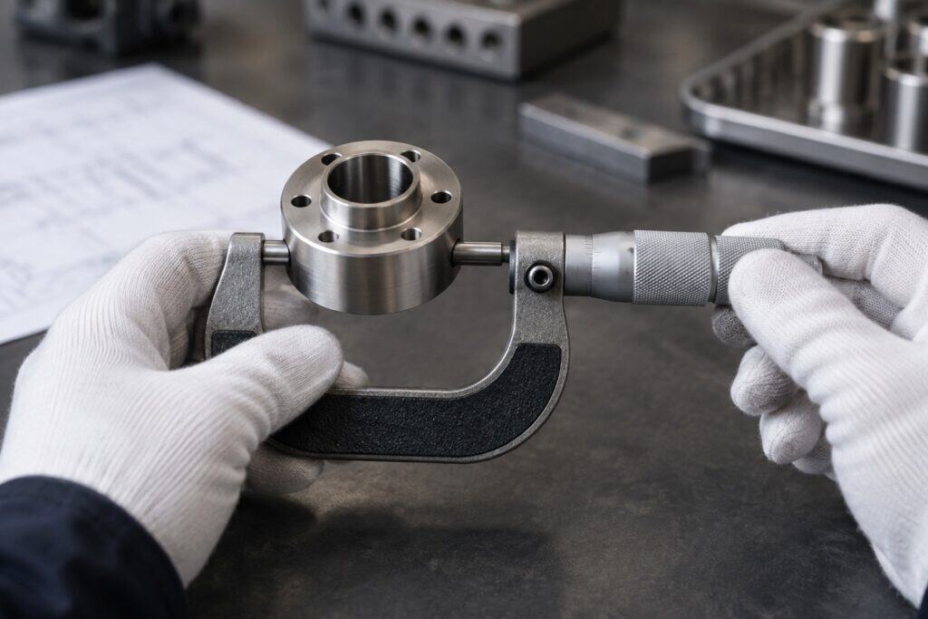
Electroless Nickel Coating Thickness Tolerances
Accurate coating thickness is important to allow adequate assembly tolerance. Because electroless nickel coats uniformly over all surfaces, it is a popular coating for precision parts. However, even coating and exact coating are not synonymous. Here is an explanation of realistic coating thickness and tolerance, reasons for coating variation, and a description of how to call out coating on a part’s drawing so that the plater can meet it and the inspector can check it.
Typical thickness ranges
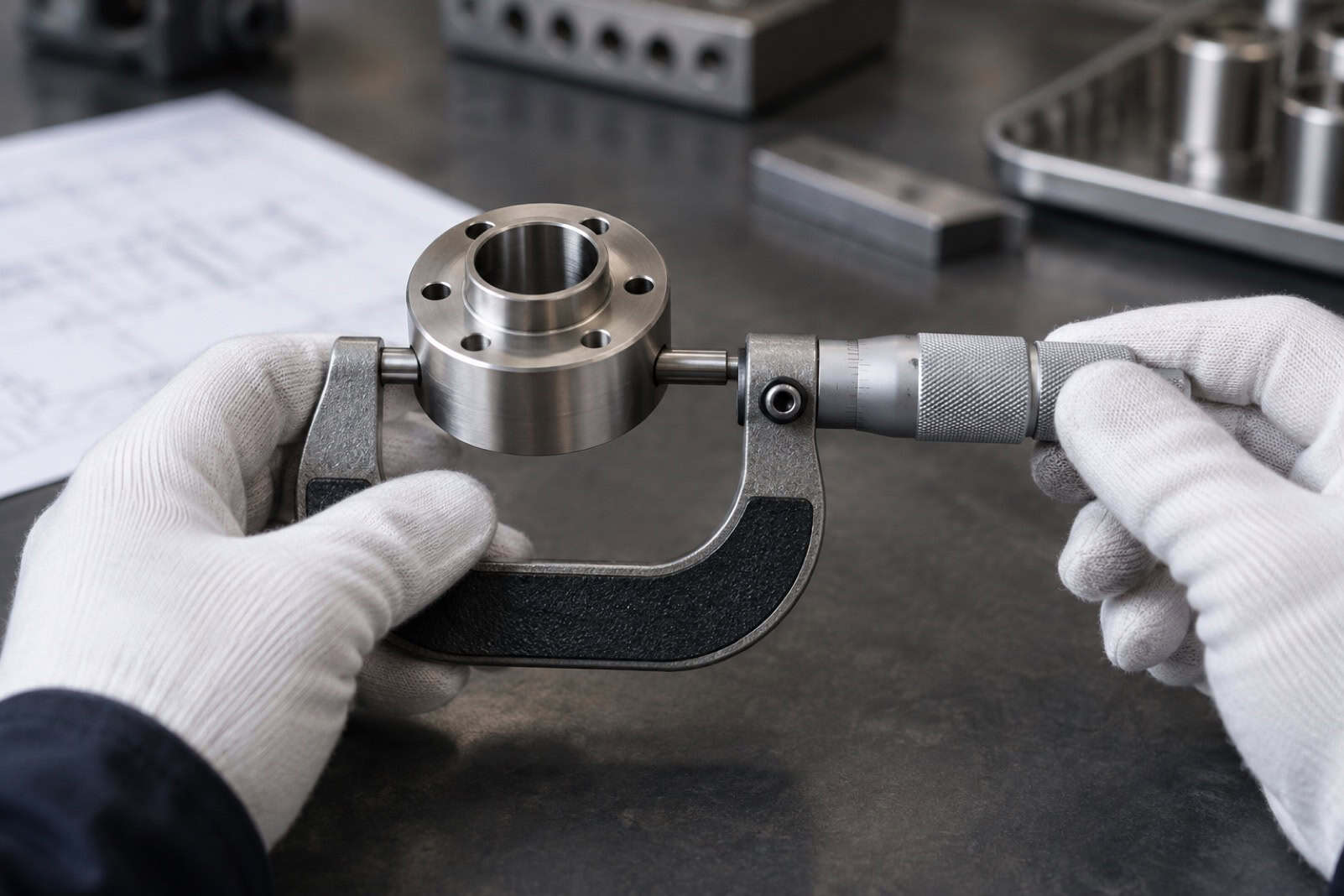
General-purpose electroless nickel plating films are typically built in roughly the 10-50 micron range. On simple external surfaces, controlled plating baths will often hold a film thickness tolerance of a few microns either way. Holding one or two microns of thickness tolerance is only possible on simple part shapes under very strict control, and the cost and delivery time increase rapidly as the thickness tolerance is reduced. If the part fit requires the very last micron, consider plating to oversize and then having the part finished.
How geometry affects build-up
Because electroless nickel plating does not use electric current, it does not suffer from the thick-at-the-edges, thin-in-the-corners problem associated with electroplating. However, coverage can be affected by the penetration of fresh plating solution to surfaces of the part to be plated. Deep narrow bores and blind holes may receive noticeably less plating than external surfaces and this under-plating can increase with depth of the bore or hole. Sharp edges of parts can receive slightly more plating than other surfaces near to the edge.
For that reason, a single nominal thickness for a part is almost never sufficient. State which surfaces you consider critical. Specify a minimum thickness for each of these surfaces and indicate where on that surface you intend to measure.
Phosphorus content and magnetism
The phosphorus content of electroless nickel can vary, and this changes its properties. The coatings are often classified into three groups of compositions.
| Type | Phosphorus | Main strengths | Magnetic as plated? |
|---|---|---|---|
| Low phosphorus | About 1 to 5% | Hardness, wear resistance | Yes |
| Medium phosphorus | About 6 to 9% | Balanced properties, bright finish | Weakly |
| High phosphorus | Over about 10% | Corrosion resistance, especially in acids | No |
Heat treatment, often used to increase hardness, can change these properties, so note whether figures relate to the coating as plated or after heat treatment.
How thickness is measured
The most suitable method for checking coatings on base materials depends on both the coating and the base material. A non-magnetic high-phosphorus layer on steel can be quickly checked by means of a magnetic induction gauge as the gauge measures the non-magnetic coating on a magnetic base. Magnetic low-phosphorus coatings on steel are not suitable for this type of test. Handheld gauges should be treated as approximate quick checks only.
X-Ray Fluorescence is typically a ‘pin-point’ measurement on the surface of the part, made without touching it, and will also report the phosphorus content, which makes it the usual choice for very tight tolerances. A metallographic cross-section is the definitive method to measure a part (where a sample is cut, polished up and then measured under a microscope). However, the sample is destroyed in the process.
Relevant techniques and standards on coating thickness measurement methods are published by the National Physical Laboratory. There is more on Electroless Nickel Coating at //www.poeton.co.uk/surface-treatments/plating/electroless-nickel-plating.
Writing a usable drawing callout
A callout should answer the questions a plater would otherwise have to ask. The following points need to be included.
- Whether each dimension applies before or after plating.
- A thickness range, not a single figure, in microns.
- The phosphorus band, which fixes corrosion resistance and magnetism.
- Where thickness is to be measured, such as a named datum face.
- Any heat treatment after plating and the hardness required.
- Surfaces that must be masked and left uncoated.
The callout could read: “12 to 18 µm EN, 8% P min, measured at datum face A.” Include the heat treatment and any masking requirements and this is complete.
Common mistakes
- Giving one thickness for the whole part and then measuring it inside a deep bore.
- Specifying high phosphorus for corrosion resistance and then asking for maximum hardness without heat treatment.
- Forgetting that coating adds to both sides of a feature, so a hole shrinks by twice the thickness.
- Choosing a measurement method that cannot work on that coating and base metal.
For how thickness and after-treatments decide corrosion performance on another common finish, see our guide to zinc nickel coating thickness for salt spray resistance.
A clear specification will save arguments and rework.
